Pulse Width Modulation (PWM) Output
The X9 connector’s digital outputs (9, 10, 11) can be used to send a user-configurable PWM signal.
The signal is configured using the keywords PWM0.PERIOD and PWM0.DUTYCYCLE.
PWM0.PERIOD configures the periodic time. For example, the time between two falling or two rising edges of the PWM signal in microseconds.
PWM0.DUTYCYCLE configures the duty cycle of the PWM signal. For example, the percentage of the time the digital output is high.
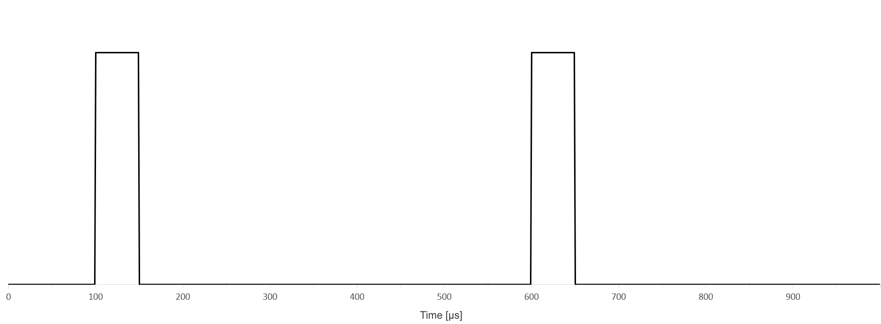
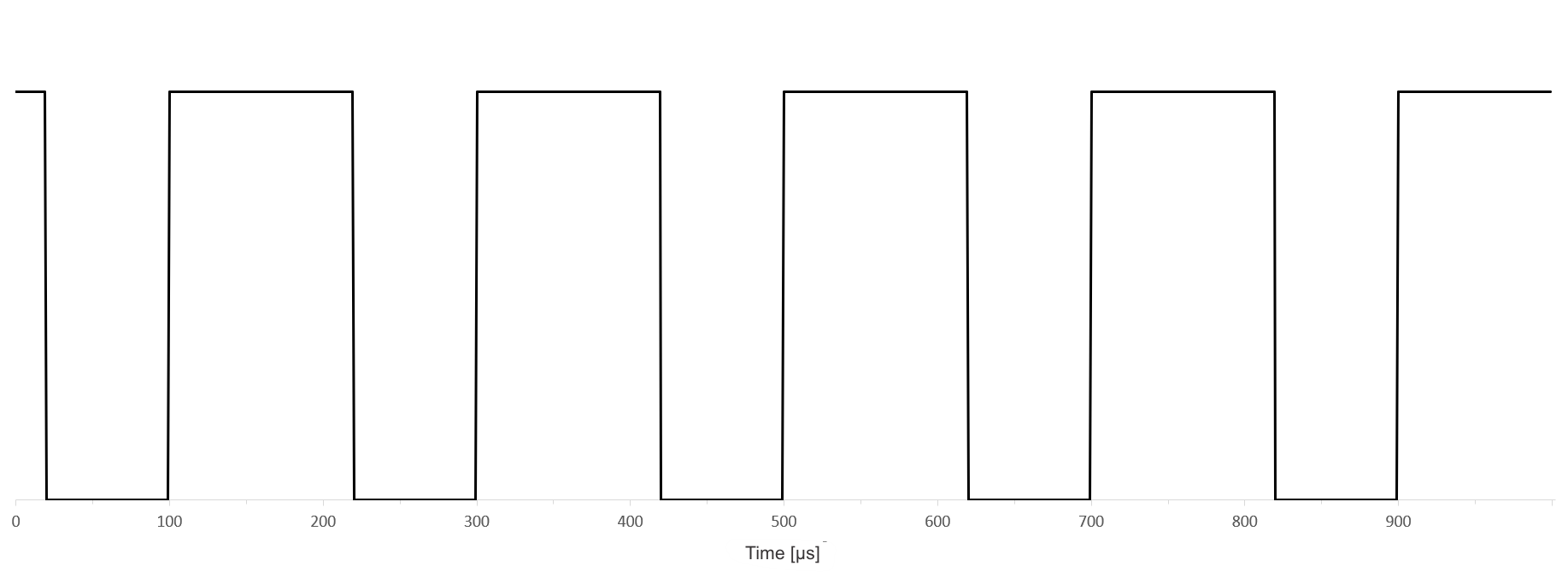
Examples:
500µs period, 10% duty cycle
200µs period, 60% duty cycle
On SynqNet drives, the additional keyword PWM0.MODE is used to give control over duty cycle and period to the fieldbus.
To output the PWM signal on one of the digital outputs on the X9 connector, the X9 configuration must be set to “General Purpose I/O” by setting DRV.EMUEMODE to 10. Then the digital I/O is used as PWM output and must be configured as an output by setting DIOx.DIR to 1. DOUTx.MODE of that output must be set to 26 to select the PWM signal.
For example, configuring digital output 9 to output a PWM with 50% duty cycle and 250 microsecond period:
--> PWM0.DUTYCYCLE 50
--> PWM0.PERIOD 250
--> DRV.EMUEMODE 10
--> DIO9.DIR 1
--> DOUT9.MODE 26